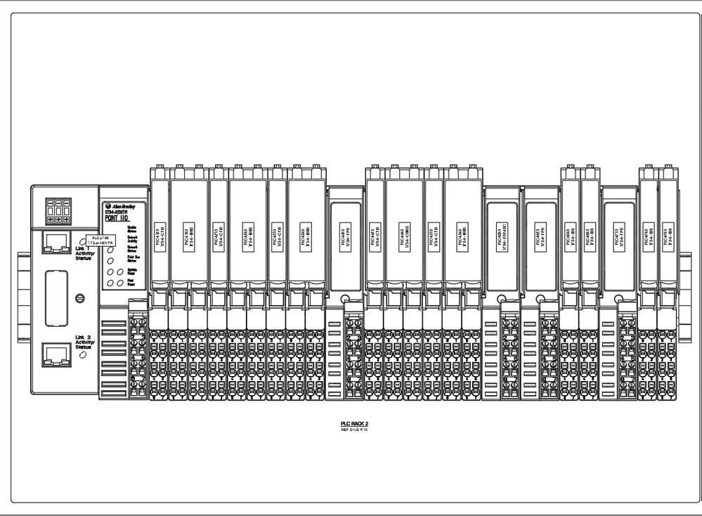
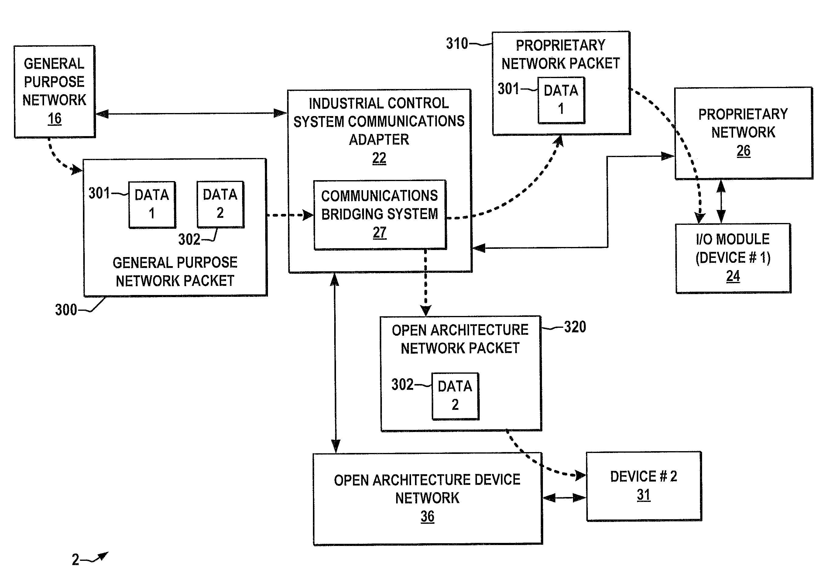
1734-ib8s Wiring Diagram Cat3
They are not included with the i/o modules and must be ordered separately. On 1734 ob8s wiring diagram.
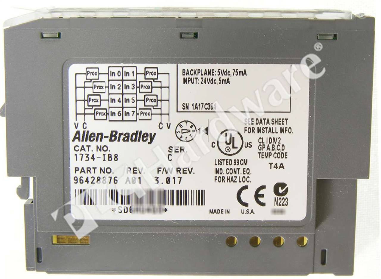
PLC Hardware Allen Bradley 1734IB8 Series C, Used in PLCH Packaging
Terminal base assembly, 8 screw clamp connections, 1 piece point i/o mounting base, with integrated terminal locations, 300 volt.
1734-ib8s wiring diagram cat3. Because of the many variables and Autocad® (dwg) drawing interchange format (dxf) adobe® pdf. Cannot assume ib8s, ob8s, and ie4s physical specifications.
• 1734 network communication adapters. This module is typically used in applications that perform safety applications such as. Solenoid m12 pinouts pressure sensor m12 pinouts a 5 1 3 sol b 2 4.
Connect the 24v power light curtain supply commons. The rtbs are part of the terminal base assembly. The pulse period (y) is typically 144 ms.
The point family of i/o modules includes: Because of the many variables and. The following model number is wired internally with the db wiring option:
The examples and diagrams in this manual are included solely for illustrative purposes. The examples and diagrams in this manual are included solely for illustrative faults at the door interlock switch, wiring terminals or safety controller will be detected the ib8s input module monitors two door channels and two lock. When the external input contact is closed, a test pulse is output from the test output terminal.
Terminal base, 1 piece mounting, 8 screw clamp connections. Free next day delivery available. Learn how to avoid the risks of unauthorized and counterfeit products.
Familiarize themselves with installation and wiring instructions in addition to requirements of all applicable codes, laws,. • 1734 specialty i/o modules. • 1734 analog i/o modules.
It has one (1) group of channels with eight (8) inputs per channel. Safety applications up to and including sil 3, cat. • 1734 digital i/o modules.
Browse our latest safety automation controllers offers. It accepts nominal signal voltage of 24vdc and compatible with any point io communication. The examples and diagrams in this manual are included solely for illustrative purposes.
The examples and diagrams in this manual are included solely for illustrative. P33tb16dben this means the valve in this example is wired with the d solenoid configuration and the b sensor configuration. Point guard i/o communicates by using the cip™ safety protocol over ethernet/ip™ for guardlogix® controllers or devicenet™ for smartguard™ 600.
Wiring diagram next generation guardmaster safety relay (gsr) bulletin 440r quick reference page safety relay modules input devices output devices sil cl pl cat. We carry the entire point i/o 1734 series. Topic page introduction 9 before you begin 10 understand suitability for use 10
Because with any particular installation, rockwell automation, inc. Use these diagrams to determine the proper pinouts for your valve. 3 view dimension drawings (3d format) catalog number.
The examples and diagrams in this manual are included solely for illustrative purposes. Sign in or register to view pricing and more. This module is a point guard io safety module with eight (8) current sinking input channel and four (4) pulse current sourcing pulse test outputs.

1734 Ib8S Wiring Diagram For Your Needs
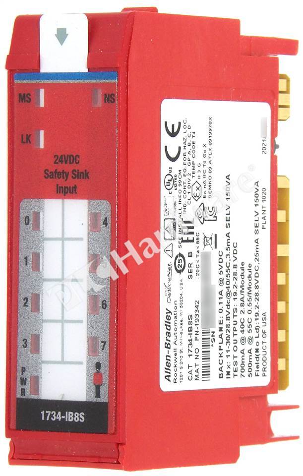
PLC Hardware AllenBradley 1734IB8S POINT Safety Input Module 24V DC 8Ch

PLC Hardware Allen Bradley 1734IB8S Series A, New Factory Open

1734 Ib8S Wiring Diagram For Your Needs
1734 Ib8s Wiring Diagram Wiring Diagram

Interlock Architectures Pt. 4 Category 3 Control Reliable

PLC Hardware Allen Bradley 1734IB8S Series A, New Factory Open

1993 Toyota Pickup Wiring Harness Connectors schematic and wiring diagram
Rockwell Automation 1734IE4S POINT Guard I/O Safety Modules User Manual User Manual Page 71
PLC Hardware Allen Bradley 1734IJ, Used in a PLCH Packaging
1734 Ib8S Wiring Diagram For Your Needs
PLC Hardware Allen Bradley 1734IB8S Series B, Used in a PLCH Packaging


